On a Quest to find Sanbot's deepest secrets – Part 7 (Bringing up the display pipeline under mainline Linux)
Last time we extracted the vendor FEX configuration and finally had all the hardware parameters we needed. Now it was time to actually use them.
The goal: get the internal 1920×1200 display working under mainline Linux 6.19.
Spoiler: it took a lot longer than expected. But we got there. Mostly.
Legal note
This research was conducted on hardware legally owned by the author. All analysis is performed for the purposes of interoperability, repair, and educational research.
No proprietary firmware or copyrighted software is redistributed on this site.
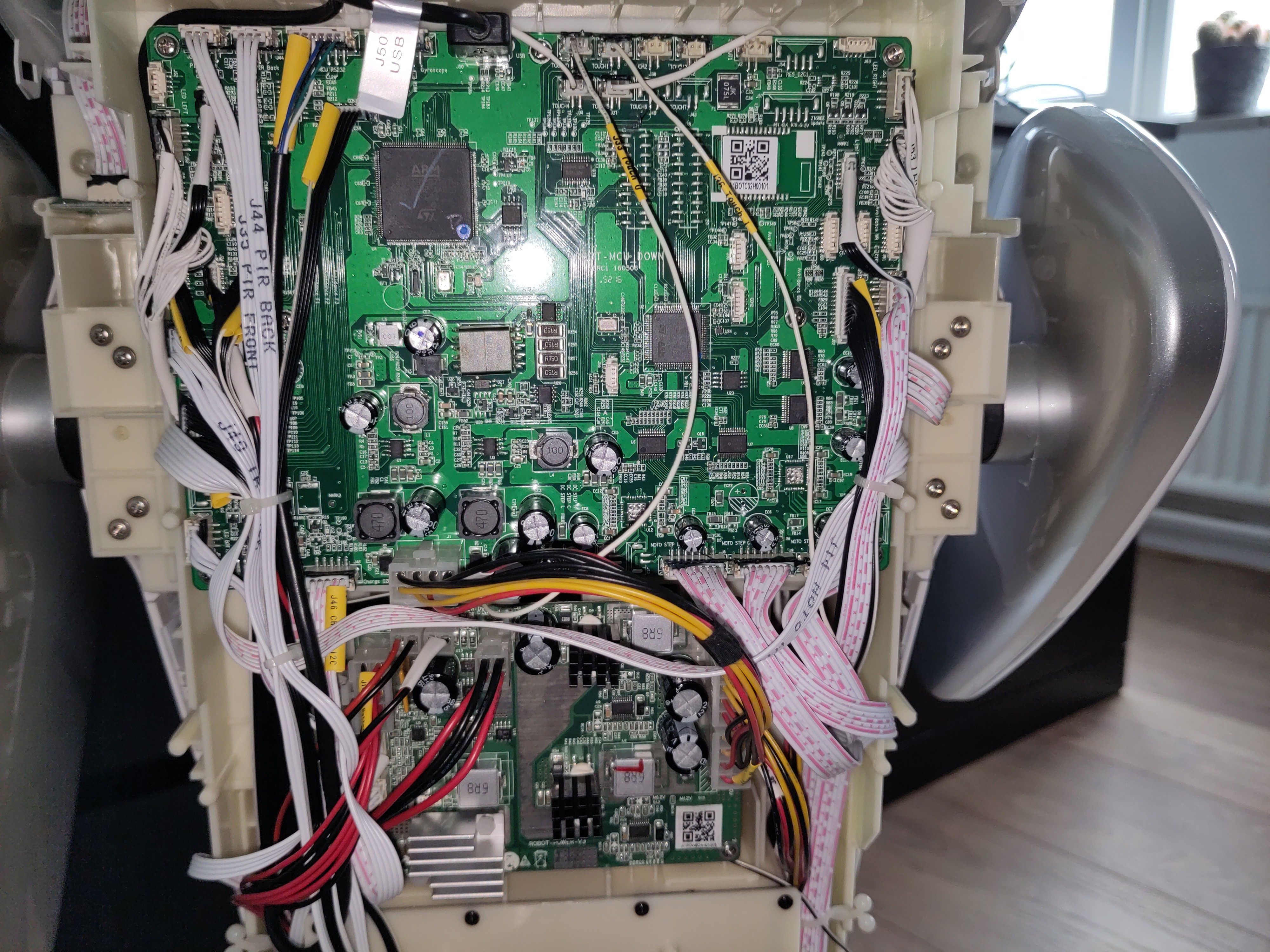
The hardware
Just to recap what we are dealing with:
- SoC: Allwinner A83T (8× Cortex-A7)
- Display: 1920×1200 parallel RGB → SSD2828 MIPI bridge → panel
- TCON0: parallel RGB output at 150 MHz pixel clock
- Backlight: PWM channel 0 on PD28, enable on PD29
- SSD2828 SPI: SCLK=PE5, MOSI=PE6, CS=PE7, RESET=PE9
The SSD2828 is a bridge chip. TCON0 outputs raw parallel RGB, the SSD2828 converts it to MIPI DSI, and the panel receives MIPI. Without initialising the SSD2828 over SPI, the panel sees nothing.
This detail will become very relevant later.
Writing the device tree
The first task was translating the FEX parameters into a proper Linux device tree.
This is not as straightforward as it sounds. The FEX format is flat. The Linux DRM pipeline is a graph of connected components:
DE2 mixer → TCON0 → [endpoint] → panel-dpi → backlight (PWM)
Every link in that graph has to be expressed as a port / endpoint pair
in the DTS. Get one wrong and the whole thing silently fails.
The first few iterations produced this delightful message:
sun4i-drm display-engine: No panel or bridge found... RGB output disabled
To debug what was actually in the compiled DTB, the kernel's own dtc was
used (the system one couldn't decompile the blob at all):
output/build/linux-6.19.8/scripts/dtc/dtc -I dtb -O dts \
    output/images/sun8i-a83t-sanbot.dtb 2>/dev/null \
    | grep -A 20 'lcd-controller@1c0c000'
Which revealed:
lcd-controller@1c0c000 {
    ...
    ports {
    };   ← empty!
};
The tcon0_out endpoint was missing from the compiled DTB entirely. After
investigation it turned out that DTC was silently dropping endpoint@0 with
reg = <0> inside tcon0_out due to an address-cells conflict. The node
was discarded without any warning.
The fix was to drop the @0 and reg entirely, a port with a single
endpoint does not need addressing:
&tcon0_out {
    tcon0_out_panel: endpoint {
        remote-endpoint = <&panel_input>;
    };
};
One silent DTC footgun, filed away.
The Kconfig maze
With the DTS correct, the next problem was getting the drivers compiled in.
The A83T uses Display Engine 2 (DE2). The relevant Kconfig symbol is
SUNXI_DE2, which is a hidden bool, no prompt, cannot be set directly.
It is only auto-selected by MACH_SUNXI_H3_H5 and MACH_SUN50I.
Not by MACH_SUN8I_A83T.
Confirming this in menuconfig by searching for DE2:
Symbol: SUNXI_DE2 [=n]
  Depends on: ARM && ARCH_SUNXI
  Selected by [n]:
    - MACH_SUNXI_H3_H5
    - MACH_SUN50I
The fix was a one-line patch to arch/arm/mach-sunxi/Kconfig:
config MACH_SUN8I_A83T
    bool "sun8i (Allwinner A83T)"
    ...
    select SUNXI_DE2        # ← add this
With SUNXI_DE2 selected, VIDEO_DE2 has default y and activates
automatically. But that only applies to the U-Boot side. It turned out
sunxi_de2.c in U-Boot was written exclusively for the H3/H5/H6 CCM layout.
The A83T has a completely different clock controller, so the driver simply
fails to compile:
drivers/video/sunxi/sunxi_de2.c: In function 'sunxi_de2_composer_init':
sunxi_de2.c:47: error: implicit declaration of function 'clock_set_pll10'
sunxi_de2.c:50: error: 'struct sunxi_ccm_reg' has no member named 'de_clk_cfg'
After staring at the error messages for a while the conclusion was clear: U-Boot display is a dead end for the A83T. Skip it entirely and do everything in Linux where the driver support is complete.
The DTB placement problem
Buildroot was configured with both BR2_LINUX_KERNEL_INTREE_DTS_NAME and
BR2_LINUX_KERNEL_CUSTOM_DTS_PATH set at the same time:
grep -E 'INTREE_DTS|CUSTOM_DTS' .config
BR2_LINUX_KERNEL_INTREE_DTS_NAME="sun8i-a83t-sanbot"
BR2_LINUX_KERNEL_CUSTOM_DTS_PATH="dts/sun8i-a83t-sanbot.dts"
Both set simultaneously means Buildroot compiles the custom DTS from the root
arch/arm/boot/dts/ directory, without access to the DTSI files in
allwinner/. The compiled DTB was technically valid. As it had the correct magic bytes, a
plausible size. But was missing the entire DE2 display pipeline because the
DTSI nodes never made it in.
Confirmed by inspecting the compiled result:
output/build/linux-6.19.8/scripts/dtc/dtc -I dtb -O dts \
    output/images/sun8i-a83t-sanbot.dtb 2>/dev/null \
    | grep -E 'display-engine|status.*okay|1100000|mixer'
display-engine {
    compatible = "allwinner,sun8i-a83t-display-engine";
    status = "okay";
    mixer@1100000 { ...
The display-engine node was correct once the DTS was placed inside
arch/arm/boot/dts/allwinner/ and the intree name was set to
allwinner/sun8i-a83t-sanbot. The fix:
cp dts/sun8i-a83t-sanbot.dts \
    output/build/linux-6.19.8/arch/arm/boot/dts/allwinner/

# Fix includes (no longer need the allwinner/ prefix)
sed -i 's|#include "allwinner/sun8i-a83t.dtsi"|#include "sun8i-a83t.dtsi"|' \
    output/build/linux-6.19.8/arch/arm/boot/dts/allwinner/sun8i-a83t-sanbot.dts
sed -i 's|#include "allwinner/axp81x.dtsi"|#include "axp81x.dtsi"|' \
    output/build/linux-6.19.8/arch/arm/boot/dts/allwinner/sun8i-a83t-sanbot.dts

echo 'dtb-$(CONFIG_MACH_SUN8I) += sun8i-a83t-sanbot.dtb' >> \
    output/build/linux-6.19.8/arch/arm/boot/dts/allwinner/Makefile

make -C output/build/linux-6.19.8 ARCH=arm \
    CROSS_COMPILE=$(pwd)/output/host/bin/arm-buildroot-linux-gnueabihf- \
    allwinner/sun8i-a83t-sanbot.dtb
Lesson: never set both INTREE_DTS_NAME and CUSTOM_DTS_PATH at the same
time in Buildroot. Pick one.
The panel compatible string
With the DTS and DTB placement sorted, the next boot showed:
sun4i-drm display-engine: bound 1100000.mixer
sun4i-drm display-engine: bound 1200000.mixer
sun4i-drm display-engine: bound 1c0c000.lcd-controller
[drm] Initialized sun4i-drm 1.0.0 for display-engine on minor 0
Progress. But tcon0 (lcd-controller@1c0c000) was still stuck in deferred
probe. The panel had no driver bound despite CONFIG_DRM_PANEL_SIMPLE=y.
Forcing a bind attempt to see the actual error:
echo panel > /sys/bus/platform/drivers/panel-simple/bind
sh: write error: No such device
-ENODEV. The driver rejected the device entirely. Checking whether
simple-panel was in the driver's compatibility table:
grep 'simple-panel' \
    output/build/linux-6.19.8/drivers/gpu/drm/panel/panel-simple.c
No output. It is not there.
Searching for the correct compatible:
grep '"panel' \
    output/build/linux-6.19.8/drivers/gpu/drm/panel/panel-simple.c \
    | head -5
.compatible = "panel-dpi",
In mainline Linux 6.19, the correct compatible for a custom-timing parallel
RGB panel is panel-dpi. It reads its timing from the panel-timing subnode
and requires a power-supply property.
Change two lines in the DTS:
panel: panel {
compatible = "panel-dpi"; /* was "simple-panel" */
power-supply = <®_dcdc1>; /* required by panel-dpi */
...
Next boot:
panel-simple panel: Specify missing bus_format
panel-simple panel: Expected bpc in {6,8} but got: 0
sun4i-drm display-engine: bound 1c0c000.lcd-controller
[drm] Initialized sun4i-drm 1.0.0 for display-engine on minor 0
The warnings about bus_format and bpc are fixable by adding
bus-format = <0x100a> and bpc = <8> to the panel node. But the important
part: all five components are now bound and /dev/dri/card0 exists.
Checking the hardware
With modetest from libdrm-tests, listing connectors:
modetest -M sun4i-drm -c
53      0       connected       Unknown-1       0x0             1       52
  modes:
    #0 1920x1200 59.96 1920 1948 1964 2044 1200 1200 1208 1224 150000
        flags: nhsync, nvsync; type: preferred, driver
The connector reports as connected with exactly the timing from the FEX
file. The DRM driver correctly parsed the panel-timing node.
Before setting a mode, checking the panel enable GPIO state:
mount -t debugfs debugfs /sys/kernel/debug
cat /sys/kernel/debug/gpio | grep 228
gpio-228 (enable) out lo ← PH4 panel enable is LOW
Setting the mode:
modetest -M sun4i-drm -s 53:1920x1200
setting mode 1920x1200-59.96Hz on connectors 53, crtc 51
Checking again immediately after:
cat /sys/kernel/debug/gpio | grep 228
gpio-228 (enable) out hi ← PH4 panel enable is now HIGH
TCON0 is now clocking out pixels at 150 MHz. The backlight:
echo 0 > /sys/class/backlight/backlight/bl_power
echo 10 > /sys/class/backlight/backlight/brightness
The backlight illuminates. The PWM is running. The panel enable is high.
The one missing piece
Everything works. Except the screen stays blank.
The reason is the SSD2828 bridge chip.
TCON0 outputs parallel RGB. The SSD2828 sits between TCON0 and the MIPI panel and converts the signal. But the SSD2828 needs to be initialised over SPI before it will pass anything through.
The SPI lines (PE5/PE6/PE7) and reset (PE9) are all confirmed in the FEX
dump. The vendor driver is called qihan_lcd and the init sequence is
compiled into the vendor disp.ko kernel module found on the Android system
partition:
strings /mnt/android/vendor/modules/disp.ko | grep -i qihan
qihan_lcd
qihan_panel.c
drivers/video/sunxi/disp2/disp/lcd/qihan_panel.c
Extracting and reimplementing that init sequence is the next step.
The full display pipeline is working. The bridge just needs its coffee.
Current state summary
| Component | Status |
|---|---|
| DE2 mixer | ✅ bound |
| TCON0 (lcd-controller) | ✅ bound |
| HDMI (tcon1) | ✅ bound |
| panel-dpi driver | ✅ bound |
| PWM backlight | ✅ working |
| PH4 panel enable | ✅ high after modetest |
| PL10 panel power | ✅ high (r_pio) |
| SSD2828 SPI init | ❌ not yet implemented |
| Pixels on screen | ❌ blocked by SSD2828 |
What's next
The qihan_panel.c source path appears in the strings of disp.ko. The init
sequence is compiled in. The next task is extracting it, understanding the
SSD2828 register layout, and reimplementing it as either a small Linux utility
or a proper DRM bridge driver.
After that, the screen should finally show something.
To be continued…