On a Quest to find Sanbot's deepest secrets – Part 2 (USB protocol)
With part 1 ending in a dump of the Android applications running on the robot, it was time to investigate whether the robot could be controlled directly from a computer over the USB connection using the information obtained from that dump.
Legal note
This research was conducted on hardware legally owned by the author. All analysis is performed for the purposes of interoperability, repair, and educational research.
No proprietary firmware or copyrighted software is redistributed on this site.
Plugging the robot into my USB port
The first thing I had to do was partially disassemble the robot, because we need to access the internal USB port of the tablet. Where we can unplug the USB cable going to the MCU Head and body controller as well as the camera's and microphones.
After plugging in the USB cable and running lsusb the following devices appeared:
$ lsusb
Bus 001 Device 017: ID 2bc5:0401 Orbbec 3D Technology International, Inc Astra
Bus 001 Device 018: ID 05e3:0608 Genesys Logic, Inc. Hub
Bus 001 Device 019: ID 0483:5741 STMicroelectronics XXXXXXXXX-STM32 Virtual COM Port
Bus 001 Device 020: ID 1d6b:0102 Linux Foundation EEM Gadget
Bus 001 Device 021: ID 0483:5740 STMicroelectronics Virtual COM Port
From this it becomes clear that the robot exposes two USB CDC-ACM ports (VCOM) for the STM32 microcontrollers, presumably one for the head controller and one for the body controller. One 3d-camera from orbbec and Linux foundation EEM-gadget, which is the microphone and HD-camera situated in the head.
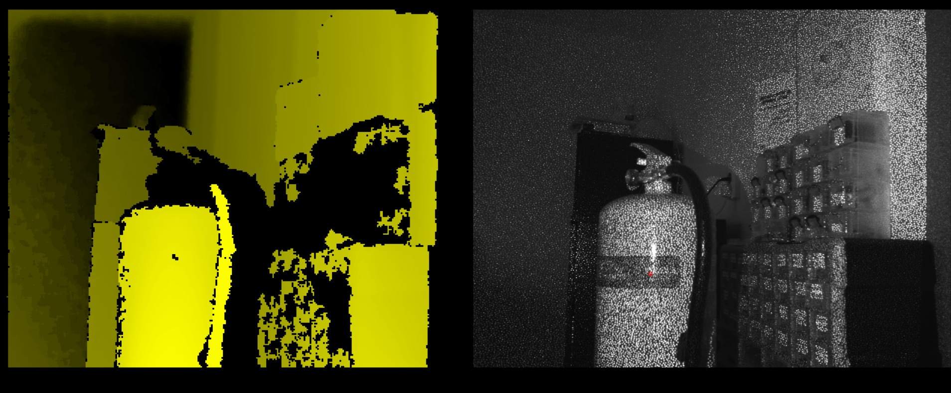
Orbbec 3D-Camera
The orbbec 3D camera matches with the astra orbbec camera driver, I found for windows on the GitHub of Vidicon Sanbot elf hacking project. And with firing up Windows, because the Linux SDK depends on very old libraries and I first wanted to get something working quickly. I was greeted with this screen using this openni-sdk. Later on when refitting this robot with new hardware/software, I will probably port the old openni-sdk to new dependencies as far as it is possible.
HD-Camera, Microphones and Zigbee
The HD-Camera, Microphones and Zigbee are handled by the EEM gadget:
Bus 001 Device 020: ID 1d6b:0102 Linux Foundation EEM Gadget
This device runs its own small Linux-based firmware which manages the HD camera and the beamforming microphone array. To get that working I did some first attempts to reverse engineer the communications and found some useful clues. Such as there is a service running on the android tablet which sends the HD camera footage over local http port 5500. Which with adb forwarding can be easily captured to your pc.
Although it is interesting, I rather leave this work for a future blog post.
Microcontrollers usb protocol
The microcontrollers are connected to the tablet via USB CDC-ACM and expose virtual serial ports over which a custom framed binary protocol is sent.
The protocol has the format:
+--------------------+------------------------------+
| 16-byte header     | Content section              |
+--------------------+------------------------------+
The header consists of:
| Offset | Size | Field | Example | Description |
|---|---|---|---|---|
| 0 | 2 | type |
A4 03 |
Message type (Java short -23549 → 0xA403) |
| 2 | 2 | subtype |
00 00 |
Usually 0 |
| 4 | 4 | msg_size |
00 00 00 0C |
32-bit content length |
| 8 | 1 | ack_flg |
01 |
Ack flag |
| 9 | 7 | unuse |
00..00 |
Always zero padding |
Content section begins at offset 16
Content structure
The content section got the following structure:
|-- FRAME_HEAD (2B) --| ACK (1B) |-- MMNN (2B) --|----------- PAYLOAD (N B) -----------| CHECKSUM (1B) |
|                     |          |               |                                    |               |
| example: FF A5      | example:01 | example:00 07 | example: 04 02 00 04 00 00        | example: B6   |
LED Command Payload
|CMD|SUB|WHICH|MODE|RATE|RAND|
|04 |02 | ..  | .. | .. | .. |
Fields
| Field | Size | Description |
|---|---|---|
CMD |
1 byte | Command group. Always 0x04 for LED control. |
SUB |
1 byte | LED subcommand. Always 0x02. |
WHICH |
1 byte | Selects which LED group to control. |
MODE |
1 byte | LED color or animation mode. |
RATE |
1 byte | Speed or delay parameter for animations. |
RAND |
1 byte | Randomization count used by some animation modes. |
The payload is constructed as:
[0x04, 0x02, which_light, mode, rate, random_count]
WHICH (LED Target)
| Value | LED Group |
|---|---|
0 |
All LEDs |
1 |
Wheel LEDs |
2 |
Left hand LEDs |
3 |
Right hand LEDs |
4 |
Left head LEDs |
5 |
Right head LEDs |
10 |
Head ring |
MODE (LED Behavior)
Common values observed:
| Value | Behavior |
|---|---|
1 |
Turn LEDs off |
3 |
Red |
4 |
Green |
7 |
Blue |
19–25 |
Various blinking / flicker animation modes |
RATE
Controls animation timing.
Typical usage:
| Value | Meaning |
|---|---|
0 |
Default speed |
>0 |
Increasing delay / slower animation |
RAND
Randomization parameter used by certain animation modes.
| Value | Meaning |
|---|---|
0 |
Disabled |
>0 |
Number of random iterations |
Example
Turn head ring LEDs green:
04 02 00 04 00 00
Meaning:
| Field | Value | Meaning |
|---|---|---|
| CMD | 04 |
LED command |
| SUB | 02 |
LED control |
| WHICH | 00 |
Head ring |
| MODE | 04 |
Green |
| RATE | 00 |
Default speed |
| RAND | 00 |
No randomness |
Summary
┌───────────────────────────────────────────────────────────────────────────────────────────────────────────┐
│                                                                                                           │
│ TYPE        SUBTYPE      MSG_SIZE         ACK     UNUSED PADDING                                          │
│ 2 bytes     2 bytes      4 bytes          1       7 bytes                                                  │
│ A4 03       00 00        00 00 00 0C       01      00 00 00 00 00 00 00                                      │
│                                                                                                           │
├──────────────────────────────────────────── Header (16 bytes) ───────────────────────────────────────────┤
│                                                                                                           │
│ FRAME_HEAD      ACK      MMNN (payload+1)      PAYLOAD (N bytes)                  CHECKSUM                │
│ 2 bytes         1        2 bytes               variable                           1 byte                  │
│ FF A5           01       00 07                 04 02 00 04 00 00                   B6                      │
│                                                                                                           │
├──────────────────────────────────────────── Content Section ─────────────────────────────────────────────┤
│                                                                                                           │
│                                  Total Frame = 22 + payload_len                                           │
│                                                                                                           │
└───────────────────────────────────────────────────────────────────────────────────────────────────────────┘